For this application we are likely to need more than the single 'insert' jack socket fitted to an audio interface or microphone channel strip.
The images on the right illustrate one low cost way of expanding the insert jack capability. (Click on either image to see a larger version).
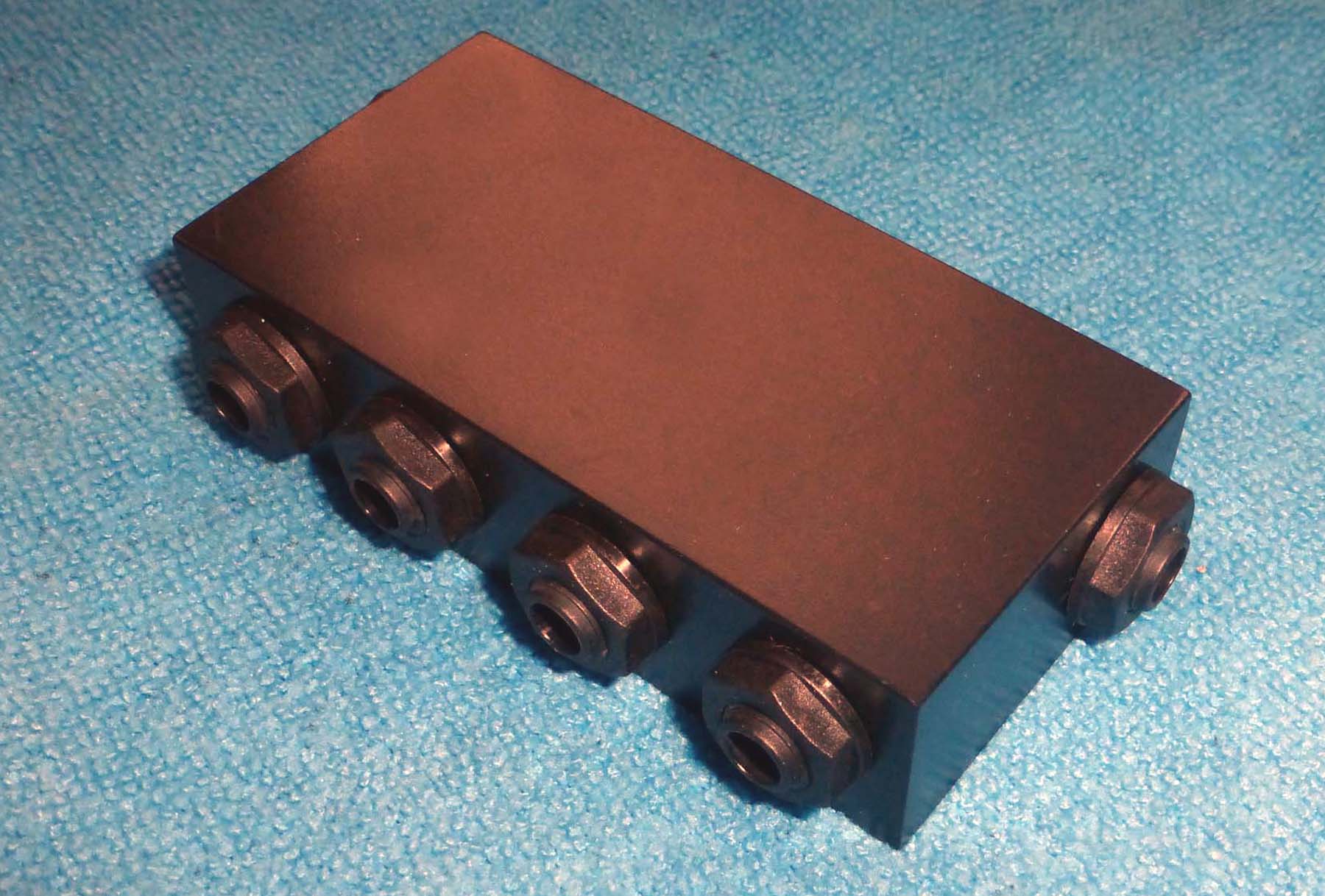
In this example 6 x switched TRS 'stereo' 1/4" jack sockets are fitted into a 100mm x 50mm x 20mm potting box.
That provides for one input jack - connected from the existing system 'insert' jack socket - and up to 5 output 'insert' jacks to connect to the EQ modules.
The switched jack 'tip and ring' terminals are linked together, so that any unused jack sockets merely allow the signal to pass though unaffected.
In the extremely unlikely event that further 'insert' sockets are required, the system can be extended infinitely by plugging in further similar jack routers to the final output socket of the previous unit.

The actual structure of the jack router is very straightforward. The image below shows the schematic of the simple circuit...

• Just click on the image above for a PDF of the schematic and connection details •
J1 is always used as the input from the 'insert jack' socket on the device being used.
The active EQ modules can be connected to any of the other jacks. The audio is processed sequentially, with the nearset connection to J1 addressed first. Unused jacks merely allow the signal to pass through unaffected.